-
System Scaffolding Overview
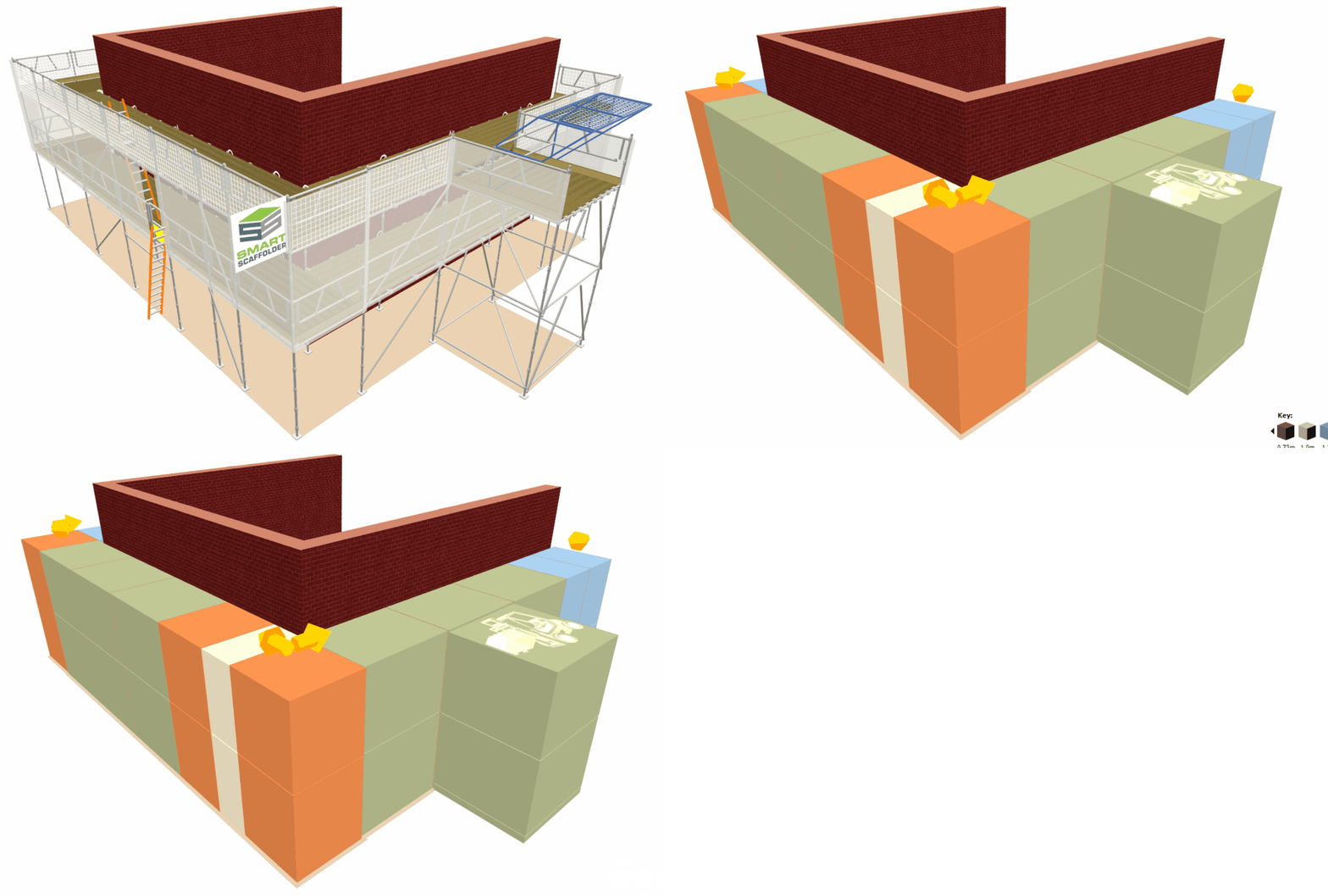
System scaffolding differs from Tube-and-Fitting scaffolding in that its components are modularised and prefabricated. This means that the scaffolding is composed of standardised bays of fixed length.
-
Accessing the Setting-Out View
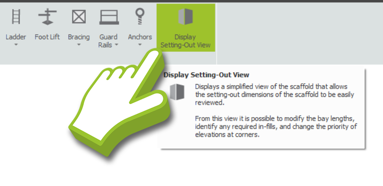
The first step is to navigate to Model IT and click on the Tools view. You will find a Display Setting-Out View button along the right-side of the Toolbar Ribbon. Click on it to enable the Setting-out View.
In the Setting-Out View, scaffold bays are represented as blocks of colour, where each colour represents one standard bay length. This makes it easy to see which bay lengths are used in the scaffold.

I cannot find the Setting-Out View?
The Display Setting-Out View can only be accessed by selecting a Scaffolding System other than Tube and Fitting. Click on the Change Scaffolding System dropdown button and select a system scaffold to work on.
-
Setting-Out Colour Key
In the bottom right corner of the screen, you will notice a colour key, which corresponds to the bay lengths on the project. You can cycle through the available colour schemes by clicking on the left and right arrows.
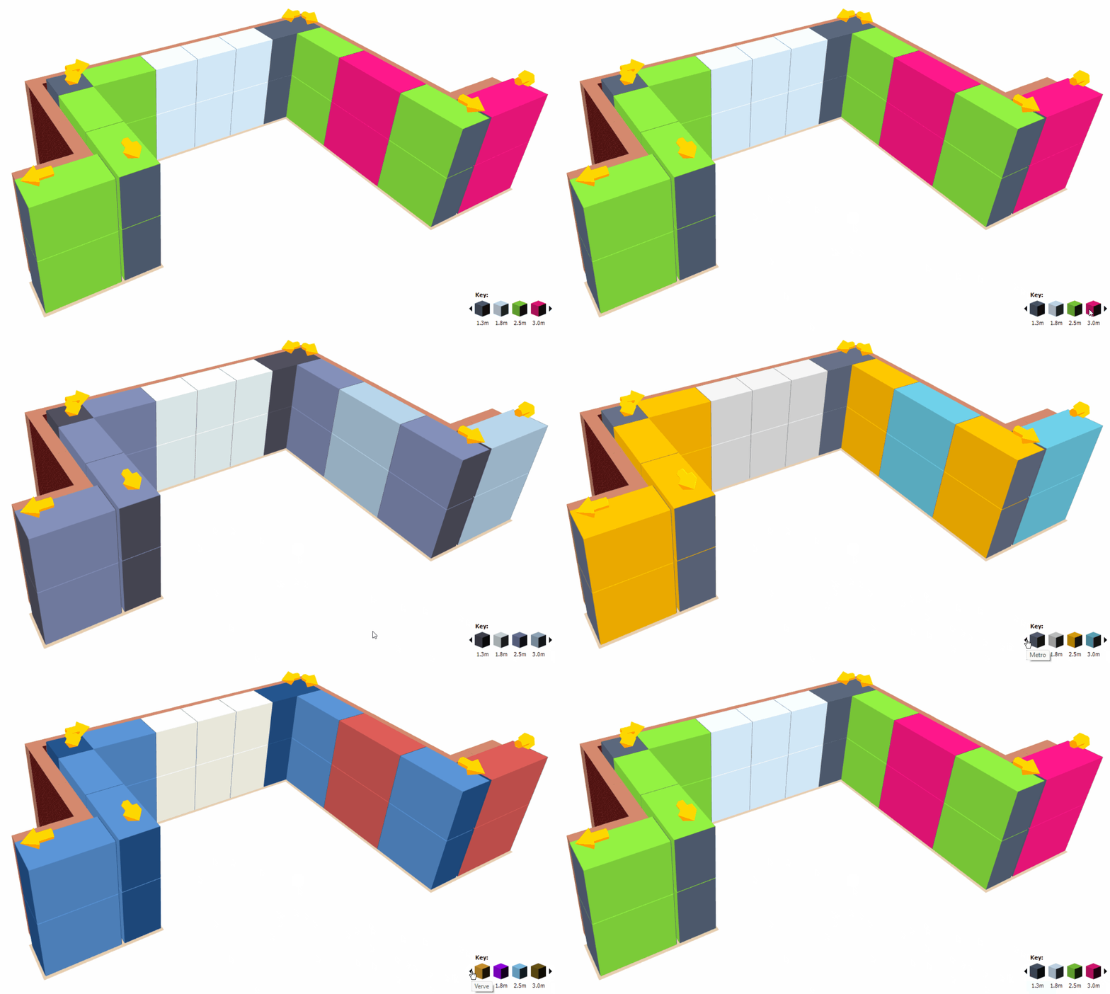
Choosing your Colour Scheme
It is recommended to choose a colour scheme that either matches your company branding or exaggerates the colours in order to make the setting-out view easier to understand.
Using the Setting-Out View On-Site
The Setting-Out view may be printed out to facilitate scaffold construction on-site. In comparison to a conventional technical drawing, the printed Setting-Out view offers a clear and tangible reference for workers on-site.
-
Configuring the Bay Dimensions
Modifying the Bay Length
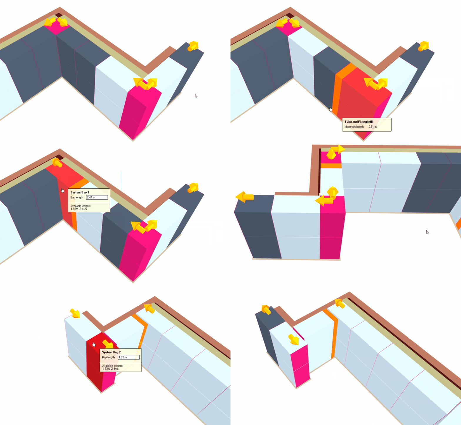
When you wish to change the Bay Length, first hover your mouse over the ledger-side of the bay you wish to modify. Once the Toolbox Dialog appears, specify the Bay Length in accordance with the ledgers available and press Enter to finalise your changes.
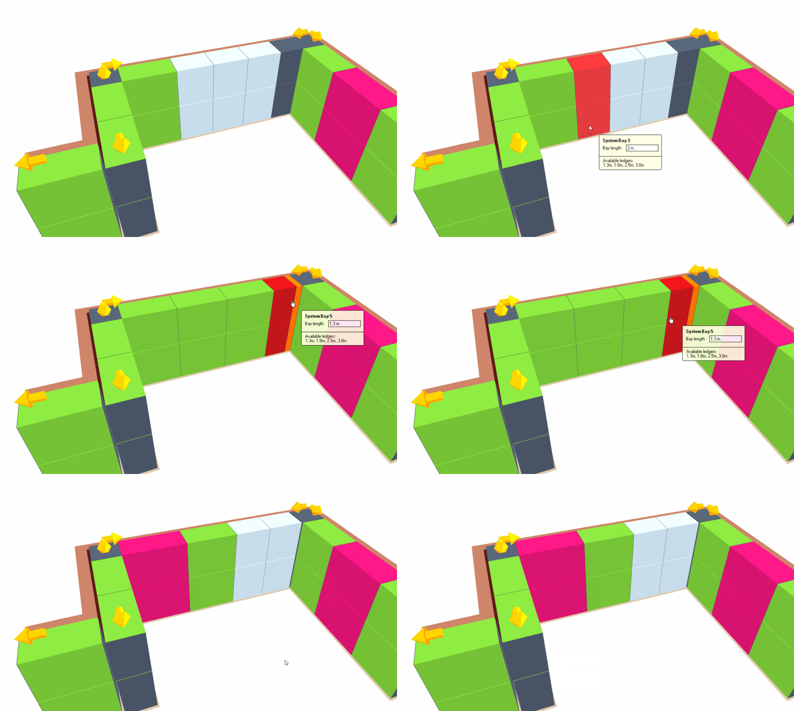
While setting-out a system scaffold around an external return, Model IT will allow the scaffold to extend past the return, but will shorten one of the bays by default to best match the building dimensions and minimise the length of the extension.
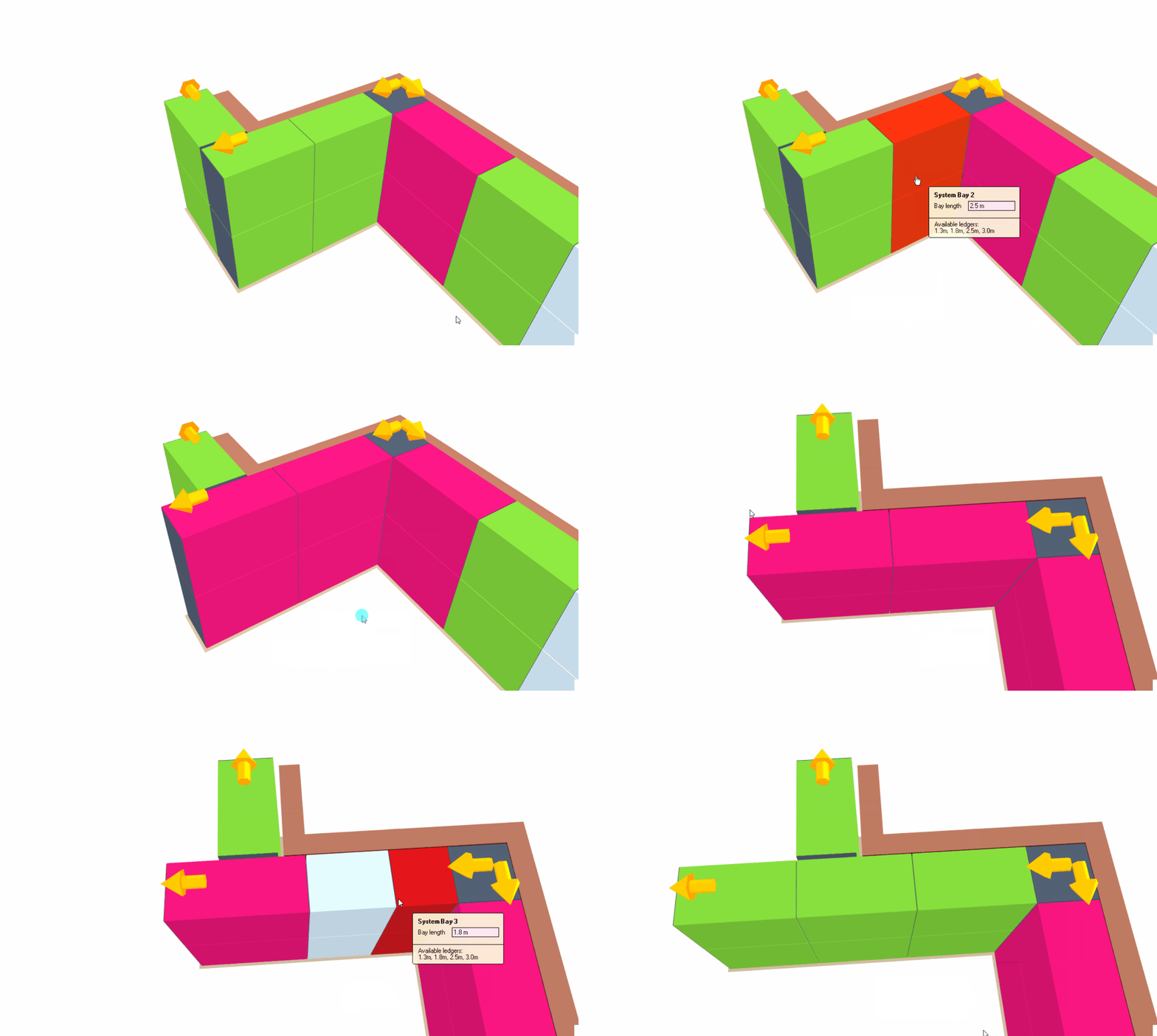
Bay Lengths are Automatically Calculated
As soon as you modify one of the bay lengths on the System Scaffold, SMART Estimator Model IT will automatically determine the optimal combination of bay lengths to fit within the available space. You can then further modify the amended bay lengths if you wish.
In particular, this is more apparent within an internal recess as the system bays must fit within the available space.
Can’t see the bay size you need?
The Setting out view will only display bay sizes available within the System configuration. If you have disabled components such as ledgers or transoms that relate to a specific bay size, that bay size will no longer show as available.
If you can’t see your bay size, head to the Material configuration and ensure all the relevant components ( E.g. Ledgers , transoms and bracing ) are enabled.
Modifying the Bay Width
When you wish to change the Bay Width, first hover your mouse over the transoms-side of the bay you wish to modify. Once the Toolbox Dialog appears, specify the Bay Width in accordance with the transoms available and press Enter to finalise your changes.
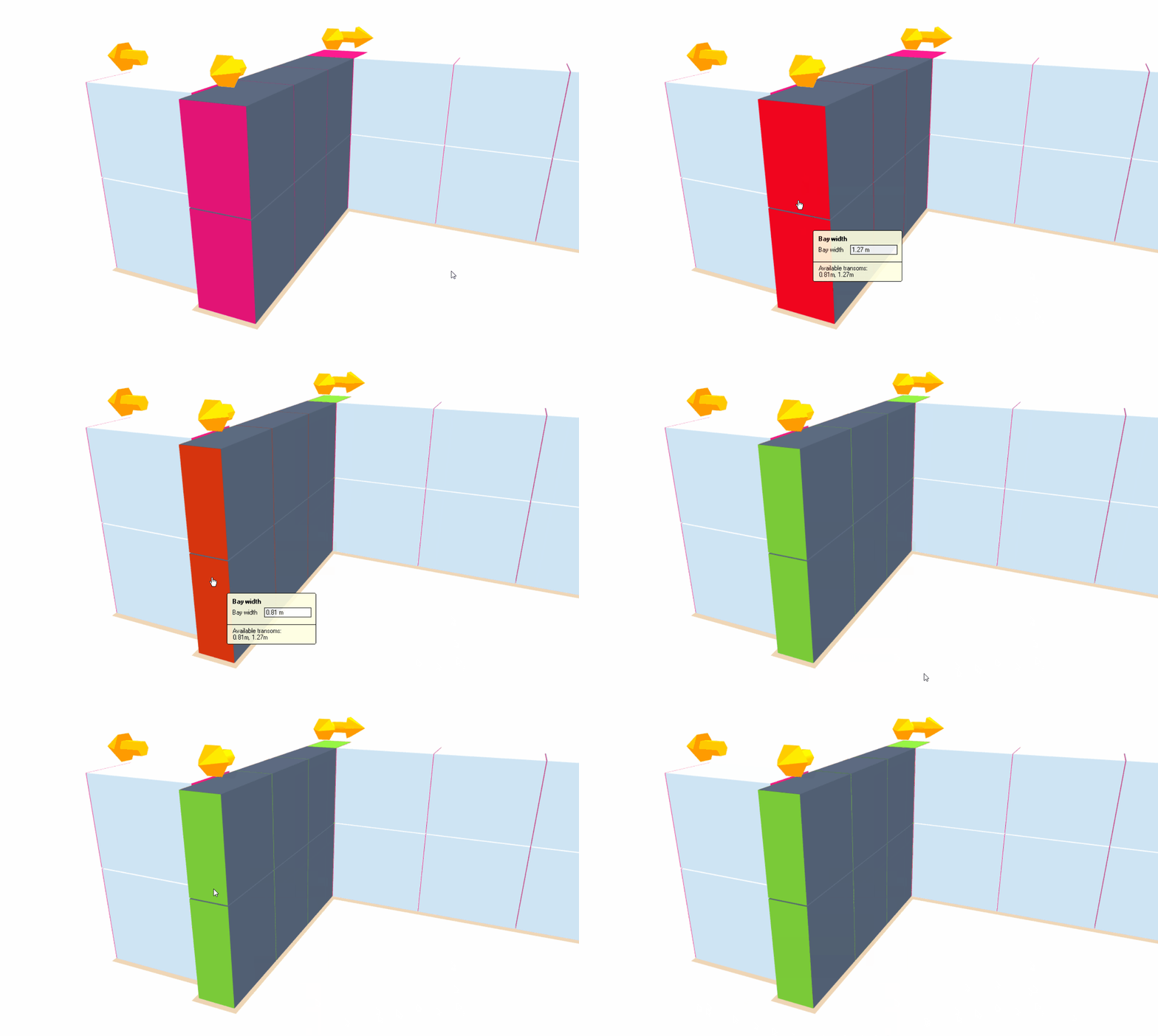
Using Schedule IT for Bay Width
If you wish, you can use Schedule IT for modifying the Bay Width. You may find this easier as it allows you to quickly adjust the Bay Width without manually navigating around the model.
Facade Gap
When you modify the Bay Length of the System Scaffold, it’ll automatically calculate what system bays should be used to erect the scaffold. This calculation is determined by the Allowable Facade Gap which is the Allowable Distance between the building and the scaffold.
From a Top-down view, you can adjust the Facade Gap by hovering your mouse between the Building or Scaffold and setting the Maximum Gap value, then press Enter to confirm your changes.
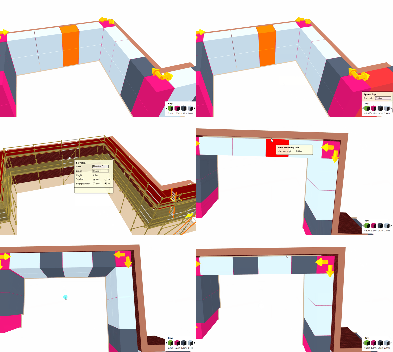
It is easier to fit in the system bays if there is a large facade gap between the building and the scaffold. However, if the scaffold is aligned closely with the building elevation, the system bays may not fit exactly within the recess.
Defining the Facade Gap for Each Elevation
If desired, you may set the maximum gap for each elevation, allowing for protrusions from the building facade to be taken into account. To set the maximum gap for one elevation, type in the required gap and press Ctrl + Enter.
Infill and Inside Boards
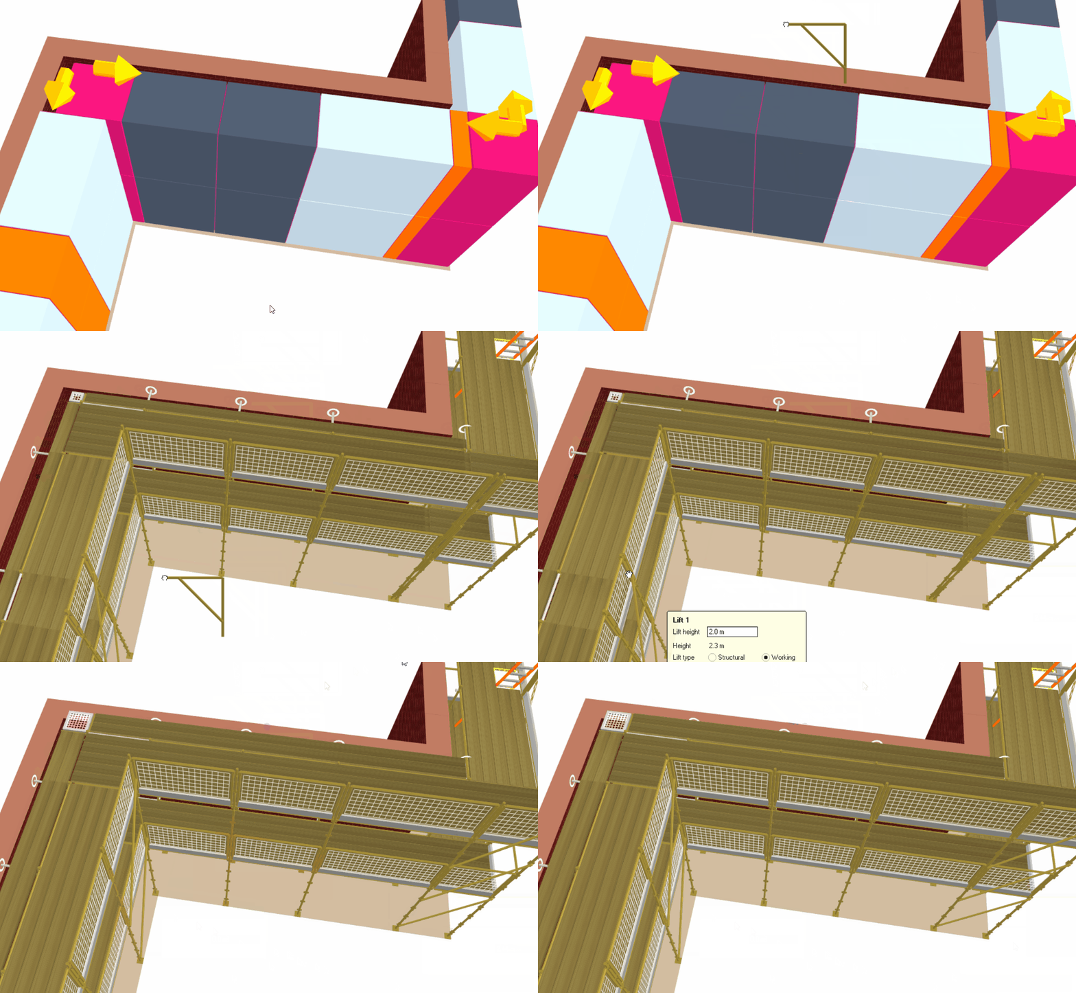
Whenever the scaffold bays do not fit exactly within the elevation, an Infill or Inside Board will be generated to fill the gap. In these cases, a bright orange block is used to identify the gap, which is filled with tube-and-fitting scaffolding by default.
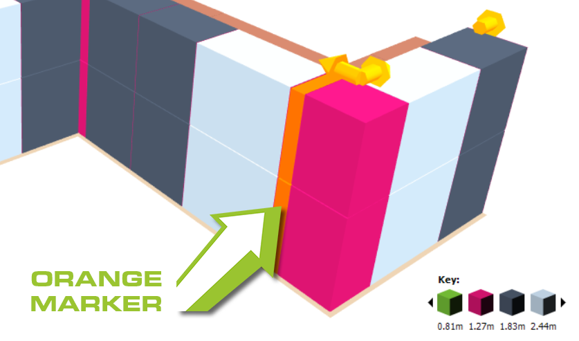
You can remove this infill by Adding an Inside Board or a Cantilever Platform to one or more elevations or by adjusting the Facade Gap. The inside boards are illustrated in the Setting-Out View so that it is clear where they have been applied.
-
Scaffold Return Priority
Finally, you may change the priority of the system scaffold at a recess or return. When the setting-out view is active, the orange Change Priority at Corner arrows can be used to determine which adjacent elevations should extend beyond the building.

Simply click on the arrows to reassign the priority for the return or recess. This will constrain or extend the bays depending on the selected priority.
Square Bay Corners
It is possible to set the corners so that the scaffold cannot extend (‘fly past’) in either direction. This will typically result in a square bay at the corner.


