Please read this before proceeding
Before you continue through this documentation, it’s recommended that you walk through the Importing the Site Plan steps. This is so you can follow along with the documentation below and do it yourself!
-
Draw Plan tool functionality overview
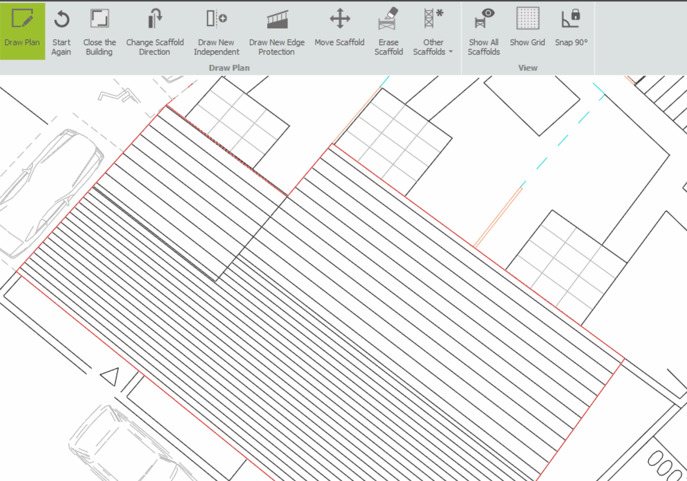
When the Draw Plan button is selected from BIM Toolbox the view switches to a plan view and displays a grid. In addition, your cursor will be accompanied by a red dot. This dot will automatically snap to the points on the grid or onto any corners, intersection or endpoint on the Vector Siteplan, this dot represents the tip of your pencil.
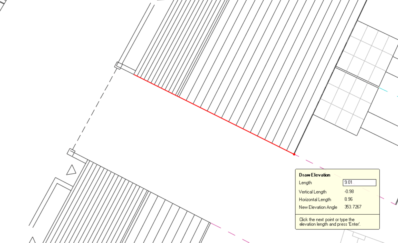
When you click and trace the siteplan, you will draw red lines that represent elevations, and drawing continuously will result in a continuous elevation. During drawing, the Length field is updated as the mouse is moved, allowing you to measure the length of each elevation.
Utilising the Draw Plan Tool with Model IT
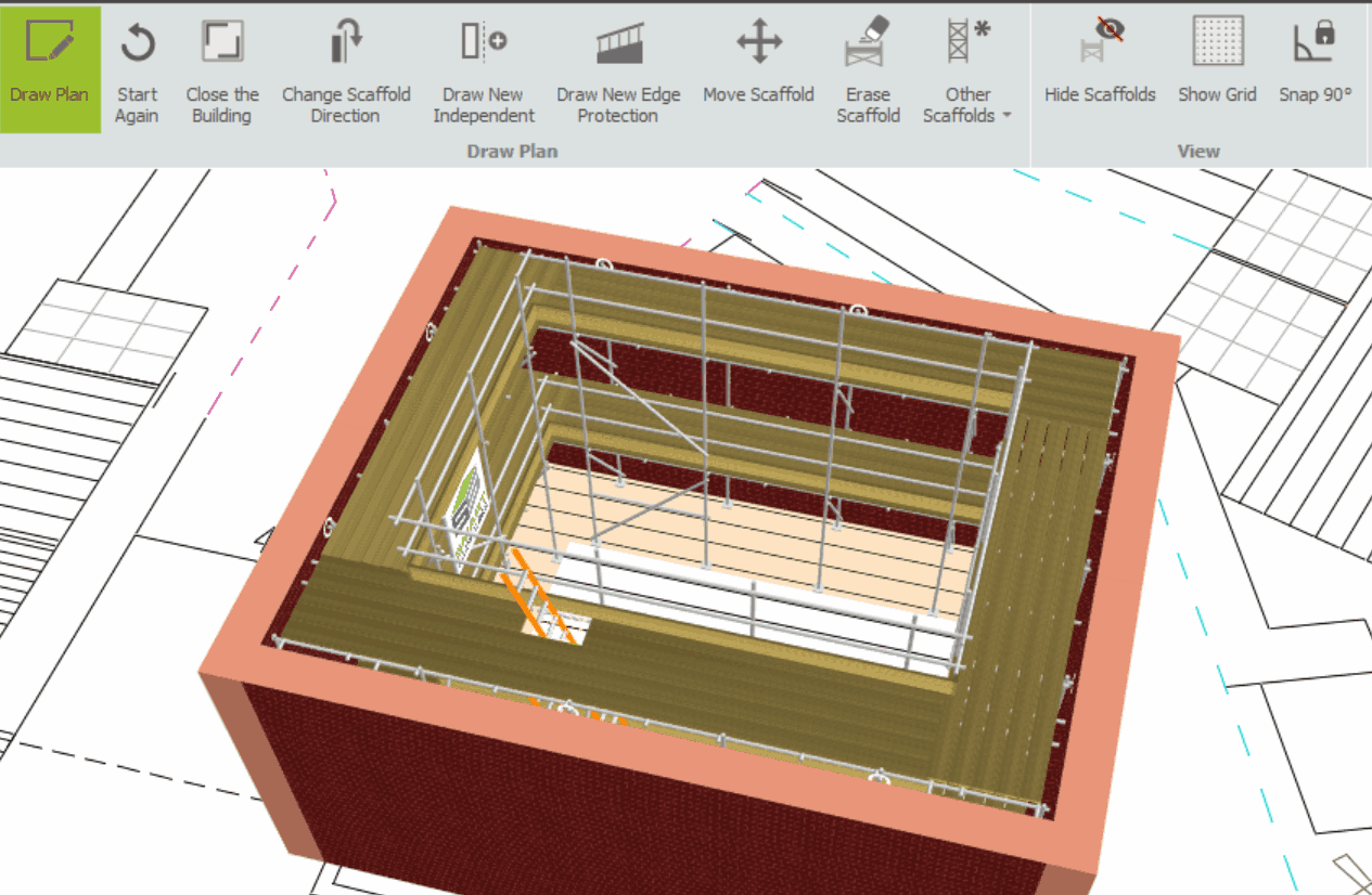
This tool is particularly beneficial for complex or irregular buildings, as well as multiple scaffolds angled at varying angles. By switching over to Model IT, you will now be able to apply any Attached Scaffolds, Add-ons, and Modifications that you wish.
-
Tracing the Site plan
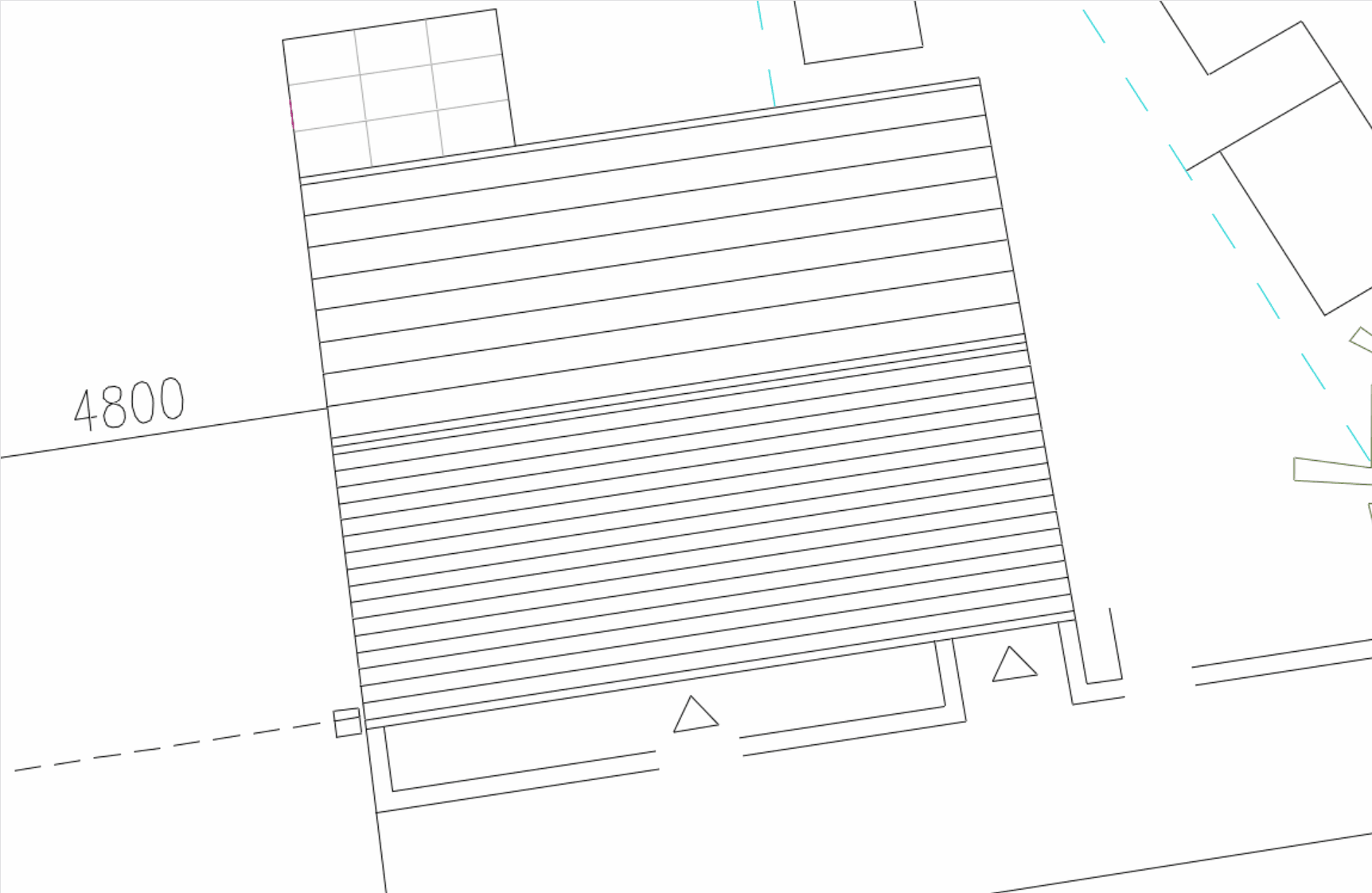
As soon as the site plan is scaled and filtered to show the correct details at the appropriate size, it is ready for use as an estimation tool. Trace the perimeter of the building you wish to create a scaffold for on the site plan by clicking on its corners.
Closing the Drawing
To make the scaffolding continuous, the final point on the building must Exactly match the first point you selected. Without a grid to guide you, this can be difficult, but you can use the Close the Building button to enclose the structure.

After reaching the last elevation, click on the Close the Building option to automatically assemble the first and last elevations into a closed structure.
-
Viewing the Scaffold
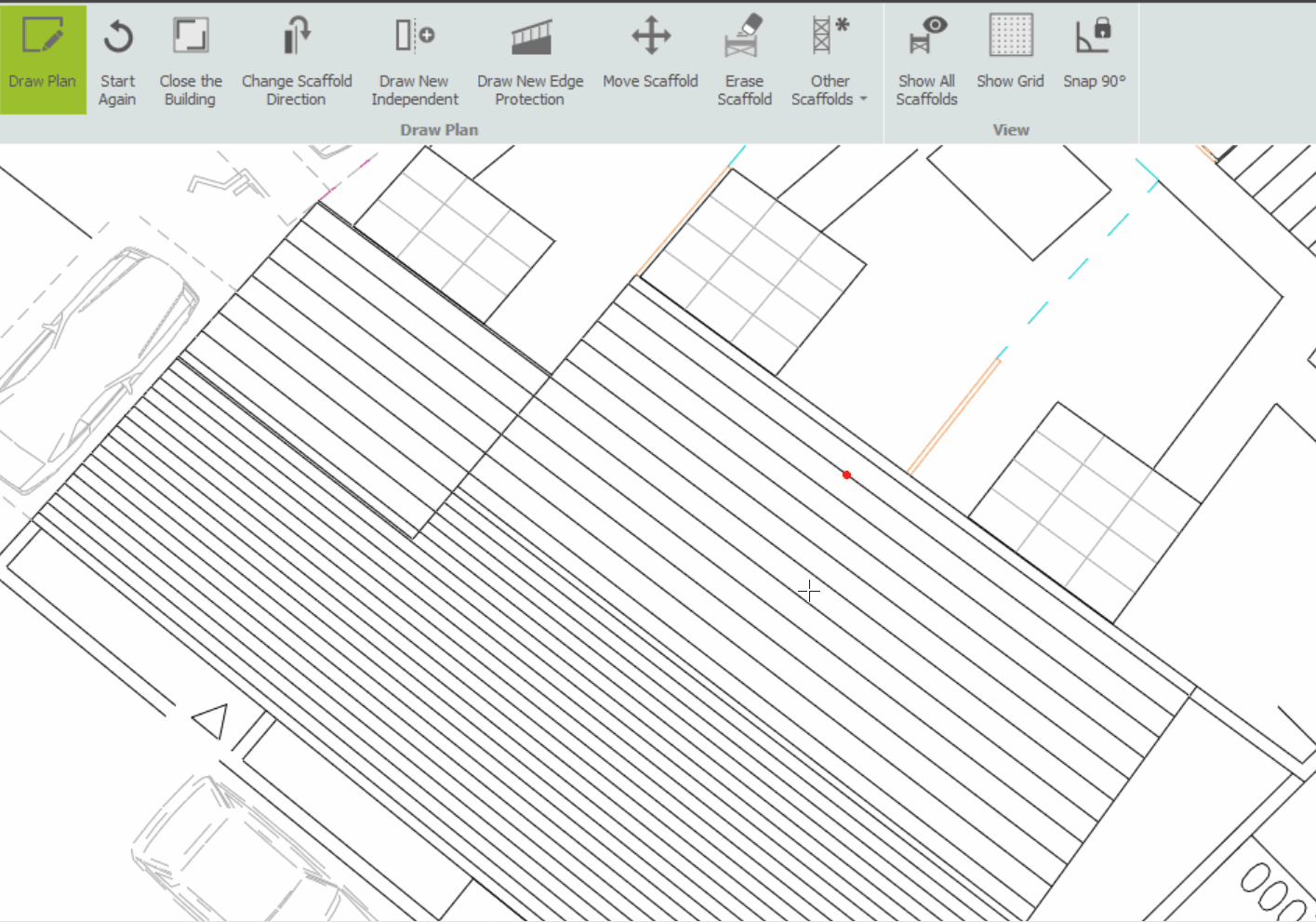
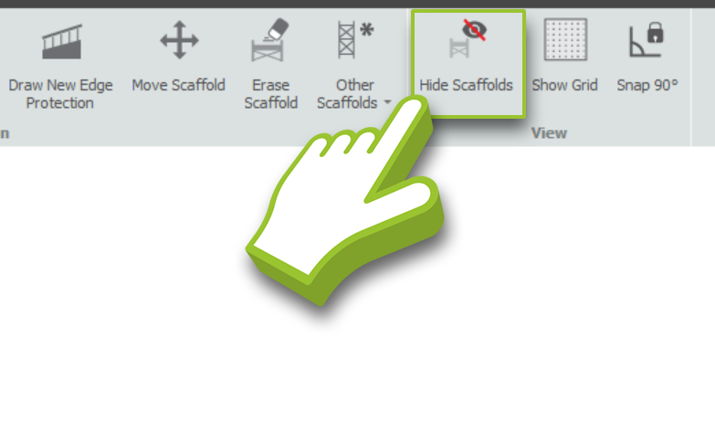
Following the tracing of the building on the site plan, scaffolds have been generated, but they are not displayed by default. If you wish to see your scaffolds, click on the Show all Scaffolds button.
Now this button will be replaced with the Hide all Scaffolds. If you want to hide all the scaffolds and remove them from the plan view, simply click on the Hide all Scaffolds button. This will give you a clear view of the site plan without any scaffolding displayed.
Is the scaffold on the wrong side?
If the scaffold is on the incorrect side of the elevation, select the Change Scaffold Direction option and click on the scaffold. By doing so, the scaffold will be moved to the opposite side of the building, which allows you to build an ‘inside’ scaffold:
This tool can be dropped on any independent scaffold even if you are not drawing an independent scaffold.
-
Type in the Length Manually
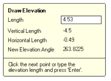
You can also type in the length and press Enter. This allows you to enter exact dimensions, including decimal places.

Unit of Measurement Description Length An adjustable measurement that shows you the exact length of the elevation being drawn. Vertical Length Shows the distance that you have moved upwards (north). Horizontal Length Shows the distance that you have moved to the right (east). New Elevation Angle Shows the angle that this elevation makes. This is always measured so that an elevation from left (west) to right (east) has an angle of 0 degrees.