The Tied independent scaffolding module is intended to perform certain design calculations for tied independent façade access scaffolds of tube and fitting construction located in the UK or Ireland. The calculation reports show the results in a transparent manner complemented by additional drawings that can be used with or without accompanying TG20:21 compliance sheets. The following sections provide details of the user inputs required, and also explain the outputs provided by the software.
SMART Compliance
Map
The program begins with a map view to allow you to input the site location, which defines the potential wind loading on the scaffold.
You can input the address in the same way as for the TG20:21 wind factor module. The site address (in the right-hand panel) is populated automatically from Google Maps services. This address can be manually overwritten if required.
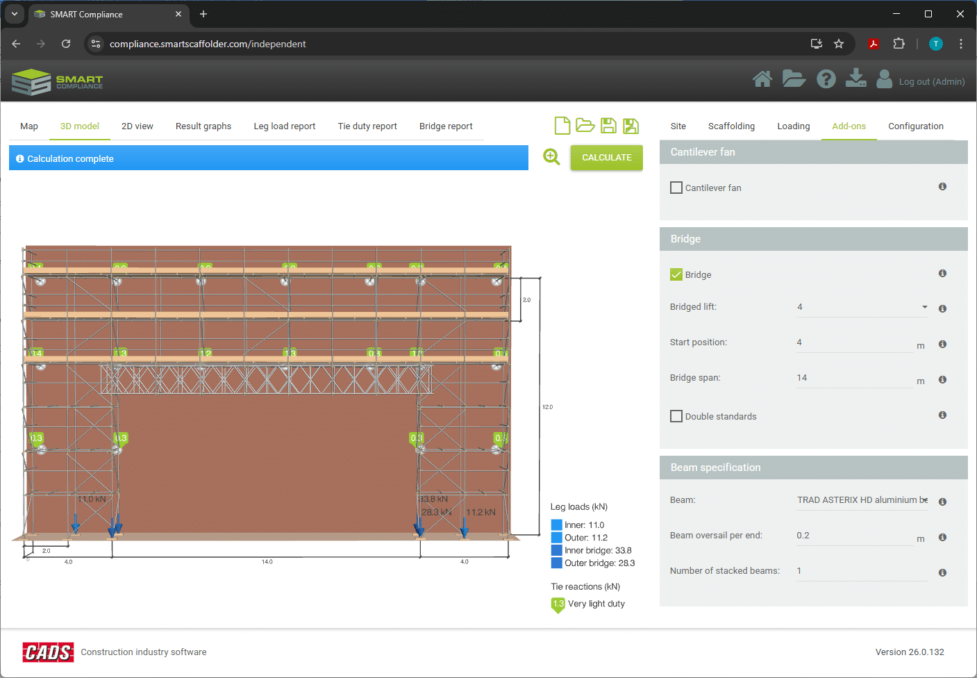
3D model
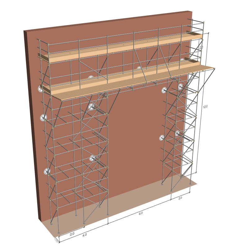
This option allows you to see the scaffold in a 3D view. Holding down the left mouse button will allow you to rotate the view. The mouse scroll can be used to zoom in or out. Holding the right mouse button will allow you to pan the view. The view also updates dynamically in response to user inputs.
2D view
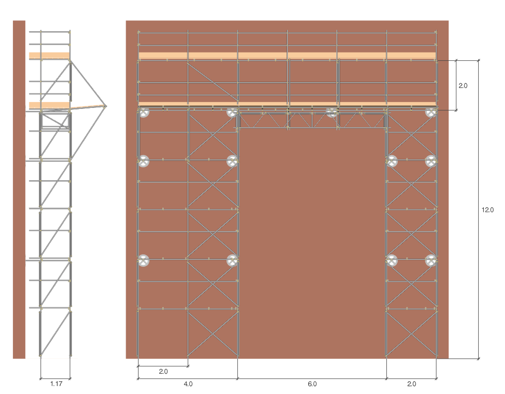
Similar to the 3D model, the 2D option will allow you to see the scaffold in a planar view (i.e. without perspective) comprising a front view and a left-hand side view. This view also updates dynamically in response to user inputs.
Results graphs
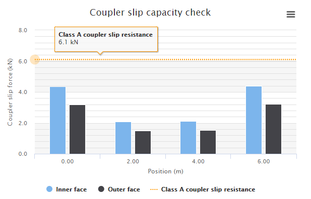
If the scaffold includes a bridge, the Results graphs tab is displayed, which contains the bridge calculation result graphs. These graphs are displayed once the calculations have been performed.
The calculation toolbar summarises the result of the bridge calculation, displaying the pass or fail result, along with any warning or error messages.
Calculation reports:
Once the analysis is complete you may view the calculation reports. There are three reports, the last of which is only available if a bridge is present.
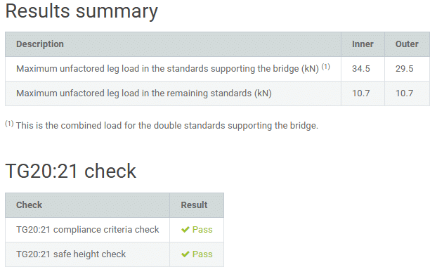
- Leg load report;
- Tie duty report;
- Bridge report.
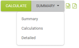
You can select between 3 levels of detail for the calculations:
- Summary report – this includes the tabular presentation of the inputs and the outcome of the calculation in the form of brief results;
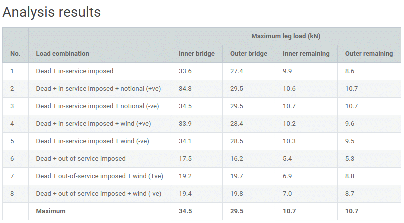
- Calculations report – this includes the presentation of the inputs used in the calculation, a 2D view of the analytical model and derivation of the loads applied to it with detailed results for each analysed load combination;
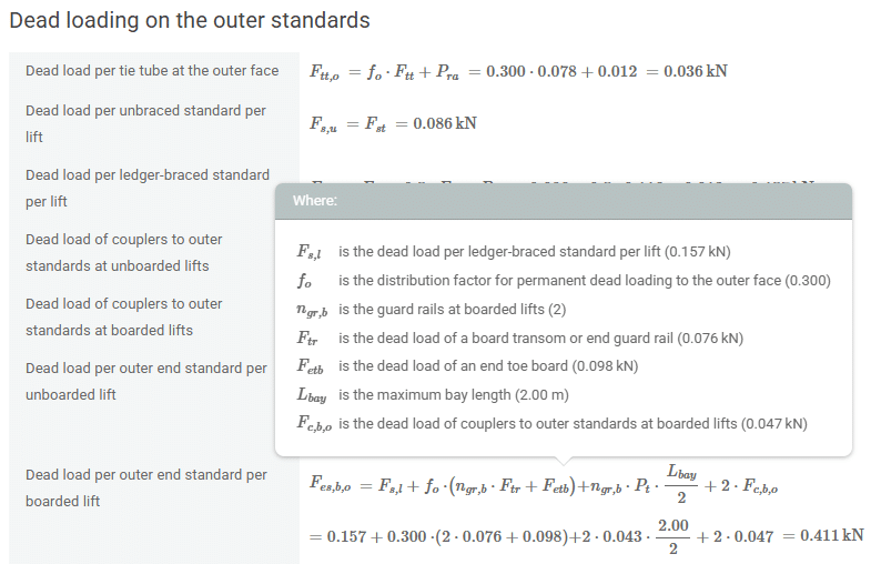
- Detailed report – this is similar to the Calculations report with load calculations presented in an algebraic and numerical form.
In this type of report, you have available an equation definition tool. By clicking on the terms of the equation a definition for each of them, along with the used value is shown.
Irrespective of the output calculation level, the Calculation report will always contain a tabular output of all the inputs used in the calculations.
You may export the calculation report either as a .docx or .pdf file by selecting the relevant icons at the top right corner, next to the calculate button.
Site:
- Site details – The site address is populated automatically from Google Maps services once the site location has been established on the map. This address can be manually overwritten if required, however, please note that the location of the site on the map will not change.
- Consider sheltering from nearby buildings – Select this option to reduce the wind exposure by considering the sheltering effects of nearby buildings. The sheltering effect is only applied to wind sectors that are calculated as being within town terrain.
- Design life – Select if the structure is a temporary structure (≤ 2 years) or if it is a long- standing/permanent structure.
- Standing during – Select the spring and summer option to reduce the wind exposure for scaffolds or temporary structures standing only between April and September. This option is applicable only if the design life is set as ≤ 2 years.
Scaffolding:
You can enter the scaffolding dimensions by selecting the Scaffolding tab, this will automatically switch the display from the map to the 3D model. The 3D model updates whenever the inputs are modified.
- Scaffold length – The length of the scaffold elevation to be considered for the calculation. Although it is possible to specify scaffold lengths up to 50 m, this will make the analysis slower and the output diagrams harder to read with no actual benefits. For the case of repeating scaffolds, there is not much change in the results when modelling more than 10 bays. Or in the case when a bridge is present, modelling more than 2 bays at each end.
- Bay length – The maximum bay length. This is limited by the load class and platform widths as in Table 2.1 of the TG20:21 Design Guide.
- Scaffold base level – The vertical distance between the ground level and the base of the scaffold, in metres, for use when the scaffold is supported on a building or other structure.
- Lift height – The maximum scaffold lift height in accordance with section 6.5 of the TG20:21 Operational Guide.
- Main boards – The maximum width of the scaffold platform in boards, in accordance with section 6.4 of the TG20:21 Operational Guide.
- Inside boards – The maximum number of inside boards, in accordance with section 6.4 of the TG20:21 Operational Guide.
- Number of boarded lifts – The maximum number of boarded lifts.
- Number of unboarded lifts – The maximum number of lifts that are not boarded.
- Cladding – You can select from the following cladding types as specified in the TG20:21 Operational Guide: Unclad, Unclad with plastic or wire brick guards, High-permeability debris-netting, Sheeting or low-permeability debris-netting.
- Inner guard rails (boarded/unboarded lifts) – Internal edge protection provided at the boarded/unboarded lifts, if required, as specified in section 6.20 of the TG20:21 Operational Guide.
- Inner toe boards – Specifies whether to provide inner toe boards at the boarded lifts (section 6.20 of the TG20:21 Operational Guide).
- Tube material – You can select the tube material from which the scaffold will be constructed. You can choose between TG20:21 compliant high-tensile galvanised steel tubes or Type 4 galvanised steel tubes (section 4.1 of the TG20:21 Operational Guide).
- Tie patterns – You can select from the tie patterns defined in chapter 7 of the TG20:21 Operational Guide.
- Structural transoms – Specifies whether structural transoms are provided as described in sections 4.5 and 6.8 of the Operational Guide, if the Automatic option is selected, structural transoms are added automatically when the calculations are performed if they are required to pass the TG20:21 check.
- Tie tube connections – Specifies whether tie tubes are connected to the inner and outer faces of the scaffold or to the inner face only. If the option is selected to connect to the inner face only, a greater proportion of the horizontal loading is transferred to the foundations at the outer face of the scaffold. If the Automatic option is selected, tie tubes are automatically connected to the outer face of the scaffold when the calculations are performed if this is required to pass the TG20:21 check.
- Additional sway resistance – Specifies whether additional sway resistance is to be provided to the scaffold as described in section 7.9 of the TG20:21 Operational Guide. If so, the proportion of the horizontal loading that is transferred to the foundation at the outer face of the scaffold is reduced. If the Automatic option is selected, additional sway resistance is automatically considered if this is required to pass the TG20:21 check.
- Top lift tied – Specifies whether to tie at the top lift at alternate standards, as described in section 7.6 of the TG20:21 Operational Guide.
- Facade permability – Specifies whether the façade to which the scaffold is tied is Impermeable (with no significant openings) or Permeable (an open structure or a façade with significant openings).
- Tie capacity is known – Specifies whether the capacity of the building fabric, anchor and tie assembly is known, as described in section 7.10 of the TG20:21 Operational Guide. If the tie capacity of the building (and tie assembly) is known, it is stated on the calculation report, compared with the tie duty and a pass or fail result is displayed. If the capacity is not yet known, the required tie duty is simply stated.
- Tie capacity – The maximum permitted tie duty capacity for the building fabric, anchor and tie assembly, as determined from the preliminary anchor testing described in section 7.18 of the TG20:21 Operational Guide and the tie assembly capacities stated in table 7.2.
You can then continue to enter the Loading on the scaffold, and any Add-ons.
Loading:
- Load class – The maximum loading on the scaffold in accordance with TG20:21 Operational Guide section 6.3.
- Inside boards load class – Specifies how the inside boards will be loaded in accordance with TG20:21 Operational Guide (section 6.3) or in accordance with BS EN 12811-1:2003 (clause 6.2.2.5).
Add-ons:
You can specify any Add-ons, if required, to the scaffold.
- Cantilever fan – Specifies whether to include a TG20:21 compliant light-duty cantilever protection fan in accordance with TG20:21 Operational Guide section 10.5.
- Cantilever fan lift – The number of the lift at which the fan is located, counting upward from ground level zero.
- Bridge – Specifies whether the scaffold will include an opening supported by a bridge beam assembly.
- Bridge lift – The number of the lift at which the bridge beam assembly is located, counting upwards.
- Start position – The start position of the bridge, defined as the centre position of the left standard supporting the bridge.
- Bridge span – The span of the bridge, defined as the centre-to-centre spacing of the supporting standards.
- Double standards – Specifies whether the standards supporting the bridge are doubled up to the beam top chord.
- Beam – Allows you to select the beam type from the available manufacturers. Alternatively, you may create a user defined beam specification if the one you want is not included in the current software version.
- Beam description – The name of the beam as it will appear in the calculation report.
- Material – The material from which the beam is fabricated.
- Depth – The centre-to-centre vertical spacing between the top and bottom beam chords.
- Section thickness – The wall thickness of the top and bottom beam chords, as specified by the manufacturer.
- Unit mass – The unit mass per beam, which should be determined from the manufacturer specification.
- Solidity ratio – The ratio of the area of the tubular components to the overall envelope area of the beam, used to calculate the wind load on the beam.
- Safe working moment/shear resistance – The maximum unfactored moment/shear force permitted for the beam, which should be determined from the manufacturer specifications.
- Maximum top/bottom restraint spacing – The maximum spacing between the lacing tube restraints at the top/bottom chords of the beams, which should be determined from the manufacturer specification. Lacing tubes attached to the beam compression chord must be stabilised by plan bracing.
- Beam oversail per end – The length the beams extend beyond the centre of the supporting standards.
- Number of stacked beams – This option allows you to stack up to 3 bridge beams in the lifts above if a single beam is not sufficient.
Configuration:
- Allow the lowest façade brace to become ineffective – This option allows the façade bracing below the first lift to become ineffective, if applicable, as described in section 5.7.3.4 of the TG20:21 Design Guide. If this option is selected and the slip capacity of the couplers connecting the façade bracing below the first lift is exceeded, the frame is reanalysed with the bracing considered ineffective. This results in a reduction to the maximum leg load at the outer face as the horizontal forces are redistributed within the frame.
- Bridge beam assembly diagram – Specifies whether the beam assembly diagram in the bridge calculation report is a 2D diagram with plan, elevation and section views or a 3D isometric diagram.
- Include analysis approach – Specifies whether to include a description of the analysis approach in the Calculation and Detailed reports.
- Minimum span/deflection ratio – The maximum permitted deflection for a bridge beam as a ratio of the beam span.
Leg load calculation
The scaffold is idealised as two 2D vertical plane frames, one for the inner and one for the outer standards and ledgers. The dead and imposed loads from the boarding are apportioned to the inner and outer frames.
Self-weights of tubes and components are also calculated and applied to the ledger and standard members. Wind forces acting in the direction parallel to the facade are also calculated.
The guard rails are not included in the stiffness analysis, but their load reactions are applied to the standards as point loads. As an exception, if the scaffold is clad with sheeting or debris netting the principal guard rails at the top lift are included as members in the stiffness analysis.
In the frame analysis, the ledgers and standards are modelled as continuous at the internal joints but discontinuous (pinned) to the orthogonal members at the outer joints. For the relevant types of loads, this idealisation gives a satisfactory correlation with the 3D analysis developed for TG20:21 which allowed for the finite stiffness of right-angle couplers.
Bridge beams are modelled as a series of continuous members with an I value given by, or deduced from, manufacturer data. The cantilever fan (if present) is not included in the stiffness analysis but its reactions are calculated by statics and applied as loads to the outer frame.
The facade bracing members are considered to be pinned to the nodes at the ledger – standard intersections. The axial stiffness of the facade brace members is reduced substantially to allow for the actual stiffness of the end couplers and typical permissible eccentricity relative to the node points. The reduction factor was established by calibration of simplified models against accurate 3D analysis of braced bays and amounts to 1/75.
The foundations/base plates of the scaffold standards are modelled as pinned lift-off supports, which requires iterative analysis in some load combinations.
The effect of ties to the facade is modelled by means of equivalent spring supports acting horizontally. The stiffness values of these supports have been established by calibration against 3D analysis models in which the tie tubes are connected to both the inner and outer ledgers with right angle couplers. The stiffness values depend on the width of the platform and whether the frame is the inner or outer relative to the façade.
The inner and outer 2D frames are subjected to a total of six load categories (in the positive and negative direction) applied horizontally in-plane:
- Notional loads of 0.15 kN applied to the nodes at working lifts as required by BS EN 12811-1 clause 6.2.3.
- Working wind loads applied to the members based on a peak velocity pressure of 0.2 kN/m².
- Out-of-service wind loads applied to the members based on the peak velocity pressure calculated for the site exposure and vertical position of the member.
All the above idealisations and approximations made to reduce complexity for 2D structural analysis have been validated against examples taken from the more accurate 3D analyses carried out during the development of TG20:21.
Tie duty calculation
The analytical model for out-of-plane loading is a 2D grillage frame in the vertical plane merging the stiffnesses of the inner and outer ledgers and standards. Pairs of unbraced ledgers and standards are represented in the 2D model as equivalent members having twice the stiffness of the actual single members. Pairs of ledger braced standards are represented in the 2D model as equivalent single members with stiffness based on the idealised lattice girder with a reduction factor applied to allow for the actual stiffness of the bracing couplers and typical permissible eccentricity relative to the node points. The effect of plan bracing of the top chords of beams is modelled in the same way. The reduction factor was established by calibration of simplified models against accurate 3D analysis of braced bays and amounts to 1/75.
The equivalent grillage members representing the pairs of ledgers and standards are modelled as continuous members at the internal joints in the stiffness analysis, as if they constituted a grillage frame with rigid joints. They are modelled as discontinuous (pinned) to the orthogonal members at the outer joints. For the relevant types of loads, this idealisation gives a satisfactory correlation with the 3D analysis developed for TG20:21 which allowed for the finite stiffness of right-angle couplers and other 3D effects.
The guard rails are not included in the stiffness analysis but in the case of unclad scaffolds their wind loads are added to the wind loads on the ledgers as an approximation for the tie loads analysis. As an exception, if the scaffold is clad with sheeting or debris netting the principal guard rails at the top lift are included as members in the stiffness analysis. The facade bracing members are considered to be pinned to the nodes at the ledger – standard intersections. The cantilever fan (if present) is not included in the stiffness analysis but its reactions on the outer frame are calculated by statics and applied as loads to the grillage.
The ties and foundations are modelled as pinned supports.
The grillage is subjected to three load categories all applied out-of-plane:
- Notional loads of 0.3 kN applied to the internal nodes at working lifts and 0.15 kN applied at end nodes as required by BS EN 12811-1 clause 6.2.3.
- Working wind loads applied to the members or cladding based on a peak velocity pressure of 0.2 kN/m².
- Out-of-service wind loads applied to the members or cladding based on the peak velocity pressure calculated for the site exposure.
All the above idealisations and approximations made to reduce complexity for 2D structural analysis have been validated against examples taken from the more accurate 3D analyses carried out during the development of TG20:21.
Axial load capacity check
The axial load capacity check for the standards supporting the bridge is a separate check, reporting whether double standards are required to support the bridge or, if double standards are insufficient, whether manual bespoke design is required.
The load capacity of the supporting standards is calculated by considering the maximum lift height below the bridge. The stated axial load capacities are for the standards supporting a bridge, inner and outer and are not applicable for other standards.
If the bridge is supported by single standards, the maximum leg load at the four standards supporting the bridge is compared with corresponding axial load capacity specified in TG20:21 Design Guide.
In the case of double supporting standards, it is assumed that the load from the bridge is supported by the supplementary standards with no load sharing with the principal standards of the double standard pair. The load from the bridge will be applied to the supplementary standard and checked against the axial load capacity of a single standard. The remaining axial load (the total leg load excluding the load from the bridge) will be applied to the principal standard and checked against the axial load capacity of a single standard.