The Loading Bay Scaffolding module calculates tube and fitting loading bay scaffolding in accordance with BS EN 12811 and TG20:21.

The Loading Bay Scaffolding module calculates tube and fitting loading bay scaffolding in accordance with BS EN 12811 and TG20:21.
All permitted TG20:21 compliant loading bay tower configurations can be calculated, including:
The calculations permit a maximum uniformly distributed load of 10 kN/m² in accordance with TG20:21 Operational Guide section 12.2.
The software checks whether the loading bay tower is TG20:21 compliant and, if so, calculates the maximum leg load for the foundation design and the maximum tie duty. The calculation will also determine:
The following sections provide details of the user inputs required, and also explain the outputs provided by the software.
The display panel options are similar to that of the Tied independent scaffolding module, with the following options available:
A map is provided to search for the site address and specify the site location. You can input the address in the same way as for the TG20:21 wind factor module. The site address (in the right-hand panel) is populated automatically from Google Maps services. This address can be manually overwritten if required.
The site wind factor is automatically calculated from the site location, in accordance with Appendix A.2 of the TG20:21 Design Guide, as also described for the TG20:21 wind factor module.
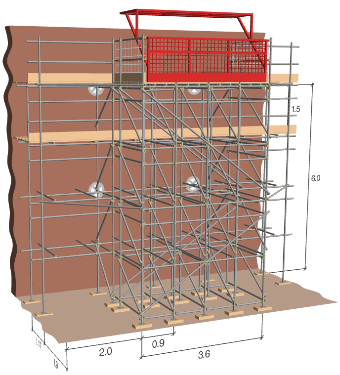
A 3D preview of the loading bay tower is displayed, with a cut-line display of the tied independent scaffold to which it is attached. The 3D preview updates as the input options are selected. Holding down the left mouse button will allow you to rotate the view, the mouse scroll wheel can be used to zoom in or out and holding the right mouse button will allow you to pan the view.
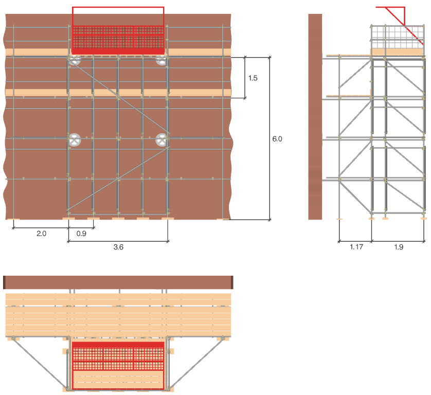
2D illustrations of the loading bay tower are provided in first-angle projection, displaying the front elevation, side elevation and plan view.
A summary report is provided when the calculations are performed, including the 2D elevations, the loading bay configuration and dimensions, the calculated leg load and tie duty, and the results of the TG20:21 check.


The following options are available for selecting the site location:
| Input | Description |
|---|---|
| Site details | The site address can be selected by searching for an address from the Search bar above the map, or by moving the site marker. This address can be manually overwritten if required, which does not alter the location of the site on the map. |
| Consider sheltering from nearby buildings | Select this option to reduce the wind exposure by considering the sheltering effects of nearby buildings. The sheltering effect is only applicable to wind sectors that are calculated as being within town terrain. |
| Design life | Select if the structure is a temporary structure (≤ 2 years) or if it is a long- standing/permanent structure. |
| Standing during | Select the spring and summer option to reduce the wind exposure for scaffolds or temporary structures standing only between April and September. This option is applicable only if the design life is set as ≤ 2 years. |
You can enter the scaffolding dimensions by selecting the Scaffolding tab, this will automatically switch the display from the map to the 3D model. The 3D model updates whenever the inputs are modified.
| Input | Description |
|---|---|
| Maximum Load |
Select the maximum permitted uniform loading on the loading bay, in kN/m², as described in section 12.2 of the TG20:21 Operational Guide. |
| Loading platform support |
Select whether the loading platform will be supported by beams or whether additional standards and bracing will be introduced to support the load, in accordance with section 12.1 of the TG20:21 Operational Guide. |
| Loading bay width |
Select the width of the loading bay platform and tower, in accordance with section 12.1 of the TG20:21 Operational Guide. |
The following inputs can be specified for the independent scaffold to which the loading bay is tied:
| Input | Description |
|---|---|
| Load class |
Select the load class of the scaffold in accordance with EN 12811-1 and TG20:21 Operational Guide section 6.3. The scaffold may be loaded to class 3 (2.0 kN/m²) or class 4 (3.0 kN/m²) if a loading bay is present. One platform may be loaded to this class and an additional platform may be 50% loaded. |
| Maximum bay length |
The maximum bay length for the scaffold, limited by the load class and platform width as in Table 2.1 of the TG20:21 Design Guide. |
| Scaffold base level |
The vertical distance between the ground level and the base of the scaffold, in metres, for use when the scaffold is supported on a building or other structure. This value should be zero if the scaffold is founded on the ground, as the elevation level of the ground is calculated automatically by the software. |
| Lift height |
The maximum scaffold lift height, in accordance with section 6.5 of the TG20:21 Operational Guide. If the scaffold lift height exceeds the maximum permitted loading bay tower lift height of 2.0 m, structural lifts will be provided. |
| Number of boarded lifts |
The maximum number of boarded lifts in the independent scaffold. |
| Number of unboarded lifts |
The maximum number of lifts that are not boarded in the independent scaffold. |
| Platform width in boards |
The maximum width of the platform of the independent scaffold, in boards, in accordance with section 6.4 of the TG20:21 Operational Guide. |
| Inside boards |
The maximum number of inside boards provided for the independent scaffold, in accordance with section 6.4 of the TG20:21 Operational Guide. |
| Cladding |
Select whether the independent scaffold to which the loading bay is tied will be unclad or whether plastic or wire brick guards (section 6.25), high-permeability debris-netting (section 6.24) or sheeting or low-permeability debris-netting (section 6.24) will be provided. All references are to the TG20:21 Operational Guide. The loading bay tower itself will be unclad. |
The following additional inputs can be provided for the loading bay tower and the façade to which it is tied:
| Input | Description |
|---|---|
| Tube material |
You can select the tube material from which the scaffold will be constructed. You can choose between TG20:21 compliant high-tensile galvanised steel tubes or Type 4 galvanised steel tubes (section 4.1 of the TG20:21 Operational Guide). |
| Facade permeability |
Specifies whether the façade to which the scaffold is tied is Impermeable (with no significant openings) or Permeable (an open structure or a façade with significant openings). |
| Tie capacity is known |
Specifies whether the capacity of the building fabric, anchor and tie assembly is known, as described in section 7.10 of the TG20:21 Operational Guide. If the tie capacity of the building (and tie assembly) is known, it is stated on the calculation report, compared with the tie duty and a pass or fail result is displayed. If the capacity is not yet known, the required tie duty is simply stated. |
| Tie capacity |
The maximum permitted tie duty capacity for the building fabric, anchor and tie assembly, as determined from the preliminary anchor testing described in section 7.18 of the TG20:21 Operational Guide and the tie assembly capacities stated in table 7.2. |